| MOQ: | 5 pcs |
| Price: | negotiable |
| Payment Method: | L/C, D/A, D/P, T/T |
| Supply Capacity: | 500 |
6.8-10.6GHz COAXIAL FILTER
Select the correct filter type –
Choose a WAVEGUIDE FILTER that matches the required response: band‑pass, low‑pass, high‑pass, or band‑stop.
Verify frequency range –
A WAVEGUIDE FILTER must have its center frequency and bandwidth aligned with your system's operating frequency.
Connect in series –
Install a WAVEGUIDE FILTER directly in the transmission line, between the source and the load.
Observe directionality (if applicable) –
Some WAVEGUIDE FILTER designs are directional; follow the arrow markings on the WAVEGUIDE FILTER.
Flange matching –
A WAVEGUIDE FILTER requires the same flange type (UG, CPR, cover, or choke) as the adjacent waveguide components.
Power rating verification –
Before operating a WAVEGUIDE FILTER, verify its average and peak power handling capabilities.
Tuning (for adjustable filters) –
Some WAVEGUIDE FILTER have tuning screws; adjust them carefully while monitoring the response on a network analyzer.
Grounding and shielding –
A WAVEGUIDE FILTER should be properly grounded to prevent spurious resonances or leakage.
| Part Number | VN-CFLT-SF-0610 |
| Operating Frequency ( GHz ) | 6.8-10.6 |
| Rejection(dB) | 50dB@13.6GHz-21.2GHz |
| Insertion Loss(dB) | ≤0.25 |
| VSWR(dB) | 1.45:1 |
| RF Connectors | SMA-F |
| Operating Temperature ( ℃ ) | 0 ~ + 55 |
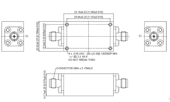
| Dimension(mm) | As below |
| ROHS Compliance | Yes |
![]()
| MOQ: | 5 pcs |
| Price: | negotiable |
| Payment Method: | L/C, D/A, D/P, T/T |
| Supply Capacity: | 500 |
6.8-10.6GHz COAXIAL FILTER
Select the correct filter type –
Choose a WAVEGUIDE FILTER that matches the required response: band‑pass, low‑pass, high‑pass, or band‑stop.
Verify frequency range –
A WAVEGUIDE FILTER must have its center frequency and bandwidth aligned with your system's operating frequency.
Connect in series –
Install a WAVEGUIDE FILTER directly in the transmission line, between the source and the load.
Observe directionality (if applicable) –
Some WAVEGUIDE FILTER designs are directional; follow the arrow markings on the WAVEGUIDE FILTER.
Flange matching –
A WAVEGUIDE FILTER requires the same flange type (UG, CPR, cover, or choke) as the adjacent waveguide components.
Power rating verification –
Before operating a WAVEGUIDE FILTER, verify its average and peak power handling capabilities.
Tuning (for adjustable filters) –
Some WAVEGUIDE FILTER have tuning screws; adjust them carefully while monitoring the response on a network analyzer.
Grounding and shielding –
A WAVEGUIDE FILTER should be properly grounded to prevent spurious resonances or leakage.
| Part Number | VN-CFLT-SF-0610 |
| Operating Frequency ( GHz ) | 6.8-10.6 |
| Rejection(dB) | 50dB@13.6GHz-21.2GHz |
| Insertion Loss(dB) | ≤0.25 |
| VSWR(dB) | 1.45:1 |
| RF Connectors | SMA-F |
| Operating Temperature ( ℃ ) | 0 ~ + 55 |
| Dimension(mm) | As below |
| ROHS Compliance | Yes |
![]()