| MOQ: | 5 pcs |
| Price: | negotiable |
| Payment Method: | L/C, D/A, D/P, T/T |
| Supply Capacity: | 500 |
14.4-15.35GHz WR-140 WAVEGUIDE COUPLER
A WAVEGUIDE COUPLER is a passive four‑port directional device that samples a fraction of the microwave power traveling in a main waveguide.
A WAVEGUIDE COUPLER consists of a main waveguide (primary line) and a secondary waveguide (coupled line), with coupling apertures or slots along their common wall.
A WAVEGUIDE COUPLER transfers a predetermined portion of the incident power from the main line to the coupled line, while the remaining power continues through the main line.
A WAVEGUIDE COUPLER operates based on the principle of wave interference and superposition through the coupling apertures.
A WAVEGUIDE COUPLER is inherently directional—it couples only the forward‑traveling wave (in the main line) to the coupled port, while the reverse‑traveling wave is coupled to the isolated port.
A WAVEGUIDE COUPLER has four ports: input port, output (through) port, coupled port, and isolated port.
A WAVEGUIDE COUPLER achieves its coupling level (e.g., 10 dB, 20 dB, 30 dB, or 40 dB) by controlling the size, number, and spacing of the coupling apertures.
A WAVEGUIDE COUPLER provides high directivity, meaning the coupled power from the forward direction is much greater than from the reverse direction.
The isolated port of a WAVEGUIDE COUPLER must be terminated with a WAVEGUIDE LOAD to absorb any unwanted reverse‑coupled energy.
| Part Number | VN-WGCP-1415-WR140-6dB |
| Operating Frequency ( GHz ) | 14.4-15.35 |
| Insertion Loss(dB) | ≤1.8 dB |
| Return Loss(dB) | ≥18 dB |
| Coupling(dB) | 6±1 |
| Isolation(dB) | ≥28 |
| Interface | WR140 (BJ140) |
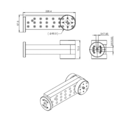
| Dimension(mm) | As below |
| Operating Temperature ( ℃ ) | -40 ~ + 80 |
| Relative humidity | 5% ~ 90% |
| ROHS Compliance | Yes |
![]()
| MOQ: | 5 pcs |
| Price: | negotiable |
| Payment Method: | L/C, D/A, D/P, T/T |
| Supply Capacity: | 500 |
14.4-15.35GHz WR-140 WAVEGUIDE COUPLER
A WAVEGUIDE COUPLER is a passive four‑port directional device that samples a fraction of the microwave power traveling in a main waveguide.
A WAVEGUIDE COUPLER consists of a main waveguide (primary line) and a secondary waveguide (coupled line), with coupling apertures or slots along their common wall.
A WAVEGUIDE COUPLER transfers a predetermined portion of the incident power from the main line to the coupled line, while the remaining power continues through the main line.
A WAVEGUIDE COUPLER operates based on the principle of wave interference and superposition through the coupling apertures.
A WAVEGUIDE COUPLER is inherently directional—it couples only the forward‑traveling wave (in the main line) to the coupled port, while the reverse‑traveling wave is coupled to the isolated port.
A WAVEGUIDE COUPLER has four ports: input port, output (through) port, coupled port, and isolated port.
A WAVEGUIDE COUPLER achieves its coupling level (e.g., 10 dB, 20 dB, 30 dB, or 40 dB) by controlling the size, number, and spacing of the coupling apertures.
A WAVEGUIDE COUPLER provides high directivity, meaning the coupled power from the forward direction is much greater than from the reverse direction.
The isolated port of a WAVEGUIDE COUPLER must be terminated with a WAVEGUIDE LOAD to absorb any unwanted reverse‑coupled energy.
| Part Number | VN-WGCP-1415-WR140-6dB |
| Operating Frequency ( GHz ) | 14.4-15.35 |
| Insertion Loss(dB) | ≤1.8 dB |
| Return Loss(dB) | ≥18 dB |
| Coupling(dB) | 6±1 |
| Isolation(dB) | ≥28 |
| Interface | WR140 (BJ140) |
| Dimension(mm) | As below |
| Operating Temperature ( ℃ ) | -40 ~ + 80 |
| Relative humidity | 5% ~ 90% |
| ROHS Compliance | Yes |
![]()