Hot Products
PRODUCTS DETAILS
Home > Hot Products >
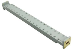
26.5-40GHz WR-28 WAVEGUIDE ATTENUATOR

26.5-40GHz WR-28 WAVEGUIDE ATTENUATOR

MOQ: 5 pcs
Price: negotiable
Payment Method: L/C, D/A, D/P, T/T
Supply Capacity: 500
Detail Information
Place of Origin
China
Brand Name
Vinncom
Certification
ISO 9000 ROHS
Model Number
VN-WGAT-2640-WR28-10dB-0.5
Part Number:
VN-WGAT-2640-WR28-10dB-0.5
Operating Frequency ( GHz ):
26.5-40
Attenuation(dB):
10
Attenuation Accuracy(dB):
±1.0
Attenuation Flatness(dB):
±0.9
VSWR:
1.10:1
Highlight:

26.5-40GHz waveguide attenuator

,

WR-28 RF attenuator

,

microwave waveguide attenuator

Product Description

26.5-40GHz WR-28 WAVEGUIDE ATTENUATOR

  • Frequency range from 1 GHz to 110 GHz+
  • Improves intermodulation distortion (IMD) performance by reducing input power to nonlinear devices
  • Flat attenuation response over frequency


How to Use a WAVEGUIDE ATTENUATOR (Usage Method)

  1. Select the attenuation type
    Choose a WAVEGUIDE ATTENUATOR as fixed or variable based on whether you need constant or adjustable signal reduction.

  2. Verify frequency range
    A WAVEGUIDE ATTENUATOR must be rated for the same frequency band (e.g., WR‑28 for 26–40 GHz, WR‑90 for 8.2–12.4 GHz) as your system.

  3. Connect in series in the transmission line
    Insert a WAVEGUIDE ATTENUATOR directly between the source and the load, with appropriate flanges on both ends.

  4. Observe directionality (if applicable)
    Most WAVEGUIDE ATTENUATOR designs are symmetrical and bi‑directional; however, some high‑power versions may have a preferred direction indicated by markings.

  5. Match flange types
    A WAVEGUIDE ATTENUATOR requires the same flange type (UG, CPR, cover, or choke) as the adjacent waveguide components.

  6. For variable attenuators – adjust the dial/drum
    Rotate the calibrated dial of a WAVEGUIDE ATTENUATOR to set the desired attenuation value; read the setting from the engraved scale.

  7. Power rating verification
    Before operating a WAVEGUIDE ATTENUATOR, verify its average and peak power handling capabilities—high‑power versions require forced air or water cooling.

  8. Thermal management
    For high‑power applications, a WAVEGUIDE ATTENUATOR should be mounted with adequate heatsinking or in a location with sufficient airflow.


Part Number VN-WGAT-2640-WR28-10dB-0.5
Operating Frequency ( GHz ) 26.5-40
Attenuation(dB) 10
Attenuation Accuracy(dB) ±1.0
Attenuation Flatness(dB) ±0.9
VSWR 1.10:1
Interface WR28 (BJ320)
Dimension(mm) As below
Handling Power 0.5CW (Watt, max)
Operating Temperature ( ℃ ) -40 ~ + 80
ROHS Compliance Yes


26.5-40GHz  WR-28  WAVEGUIDE ATTENUATOR26.5-40GHz  WR-28  WAVEGUIDE ATTENUATOR

Hot Products
PRODUCTS DETAILS
26.5-40GHz WR-28 WAVEGUIDE ATTENUATOR
MOQ: 5 pcs
Price: negotiable
Payment Method: L/C, D/A, D/P, T/T
Supply Capacity: 500
Detail Information
Place of Origin
China
Brand Name
Vinncom
Certification
ISO 9000 ROHS
Model Number
VN-WGAT-2640-WR28-10dB-0.5
Part Number:
VN-WGAT-2640-WR28-10dB-0.5
Operating Frequency ( GHz ):
26.5-40
Attenuation(dB):
10
Attenuation Accuracy(dB):
±1.0
Attenuation Flatness(dB):
±0.9
VSWR:
1.10:1
Minimum Order Quantity:
5 pcs
Price:
negotiable
Payment Terms:
L/C, D/A, D/P, T/T
Supply Ability:
500
Highlight

26.5-40GHz waveguide attenuator

,

WR-28 RF attenuator

,

microwave waveguide attenuator

Product Description

26.5-40GHz WR-28 WAVEGUIDE ATTENUATOR

  • Frequency range from 1 GHz to 110 GHz+
  • Improves intermodulation distortion (IMD) performance by reducing input power to nonlinear devices
  • Flat attenuation response over frequency


How to Use a WAVEGUIDE ATTENUATOR (Usage Method)

  1. Select the attenuation type
    Choose a WAVEGUIDE ATTENUATOR as fixed or variable based on whether you need constant or adjustable signal reduction.

  2. Verify frequency range
    A WAVEGUIDE ATTENUATOR must be rated for the same frequency band (e.g., WR‑28 for 26–40 GHz, WR‑90 for 8.2–12.4 GHz) as your system.

  3. Connect in series in the transmission line
    Insert a WAVEGUIDE ATTENUATOR directly between the source and the load, with appropriate flanges on both ends.

  4. Observe directionality (if applicable)
    Most WAVEGUIDE ATTENUATOR designs are symmetrical and bi‑directional; however, some high‑power versions may have a preferred direction indicated by markings.

  5. Match flange types
    A WAVEGUIDE ATTENUATOR requires the same flange type (UG, CPR, cover, or choke) as the adjacent waveguide components.

  6. For variable attenuators – adjust the dial/drum
    Rotate the calibrated dial of a WAVEGUIDE ATTENUATOR to set the desired attenuation value; read the setting from the engraved scale.

  7. Power rating verification
    Before operating a WAVEGUIDE ATTENUATOR, verify its average and peak power handling capabilities—high‑power versions require forced air or water cooling.

  8. Thermal management
    For high‑power applications, a WAVEGUIDE ATTENUATOR should be mounted with adequate heatsinking or in a location with sufficient airflow.


Part Number VN-WGAT-2640-WR28-10dB-0.5
Operating Frequency ( GHz ) 26.5-40
Attenuation(dB) 10
Attenuation Accuracy(dB) ±1.0
Attenuation Flatness(dB) ±0.9
VSWR 1.10:1
Interface WR28 (BJ320)
Dimension(mm) As below
Handling Power 0.5CW (Watt, max)
Operating Temperature ( ℃ ) -40 ~ + 80
ROHS Compliance Yes


26.5-40GHz  WR-28  WAVEGUIDE ATTENUATOR26.5-40GHz  WR-28  WAVEGUIDE ATTENUATOR