| MOQ: | 5 pcs |
| Price: | negotiable |
| Payment Method: | L/C, D/A, D/P, T/T |
| Supply Capacity: | 500 |
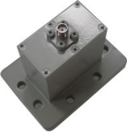
5.85-8.2GHz WR-137 WAVEGUIDE COACIAL ADAPTER
Identify the waveguide interface and coaxial connector –
A WAVEGUIDE COACIAL ADAPTER has a waveguide flange on one end and a coaxial connector (e.g., N-type, SMA, 7mm, or 3.5mm) on the other.
Match the waveguide flange type –
A WAVEGUIDE COACIAL ADAPTER requires the correct flange (e.g., UG, CPR, cover, or choke) to mate with the waveguide run.
Select the correct frequency band –
A WAVEGUIDE COACIAL ADAPTER is designed for a specific waveguide band (e.g., WR-90 for 8.2–12.4 GHz, WR-28 for 26–40 GHz); operation outside this band causes high VSWR and excessive loss.
Connect the coaxial side to the test equipment or system –
Attach the coaxial connector of the WAVEGUIDE COACIAL ADAPTER to a cable, network analyzer port, or coaxial component with the appropriate mating interface.
Verify power handling –
Before operating a WAVEGUIDE COACIAL ADAPTER at high power, confirm its average and peak power ratings; high-power designs often use air-filled waveguide sections and choke joints for thermal management.
| Part Number | VN-WGCA-0508-WR137-E-SF |
| Operating Frequency ( GHz ) | 5.85-8.2 |
| VSWR | 1.25:1 |
| Connection | SMA-50K |
| Interface | WR137(BJ70) |
| Operating Temperature ( ℃ ) | -40 ~ + 80 |
| Dimension(mm) | As below |
| ROHS Compliance | Yes |
![]()
![]()
| MOQ: | 5 pcs |
| Price: | negotiable |
| Payment Method: | L/C, D/A, D/P, T/T |
| Supply Capacity: | 500 |
5.85-8.2GHz WR-137 WAVEGUIDE COACIAL ADAPTER
Identify the waveguide interface and coaxial connector –
A WAVEGUIDE COACIAL ADAPTER has a waveguide flange on one end and a coaxial connector (e.g., N-type, SMA, 7mm, or 3.5mm) on the other.
Match the waveguide flange type –
A WAVEGUIDE COACIAL ADAPTER requires the correct flange (e.g., UG, CPR, cover, or choke) to mate with the waveguide run.
Select the correct frequency band –
A WAVEGUIDE COACIAL ADAPTER is designed for a specific waveguide band (e.g., WR-90 for 8.2–12.4 GHz, WR-28 for 26–40 GHz); operation outside this band causes high VSWR and excessive loss.
Connect the coaxial side to the test equipment or system –
Attach the coaxial connector of the WAVEGUIDE COACIAL ADAPTER to a cable, network analyzer port, or coaxial component with the appropriate mating interface.
Verify power handling –
Before operating a WAVEGUIDE COACIAL ADAPTER at high power, confirm its average and peak power ratings; high-power designs often use air-filled waveguide sections and choke joints for thermal management.
| Part Number | VN-WGCA-0508-WR137-E-SF |
| Operating Frequency ( GHz ) | 5.85-8.2 |
| VSWR | 1.25:1 |
| Connection | SMA-50K |
| Interface | WR137(BJ70) |
| Operating Temperature ( ℃ ) | -40 ~ + 80 |
| Dimension(mm) | As below |
| ROHS Compliance | Yes |
![]()
![]()